
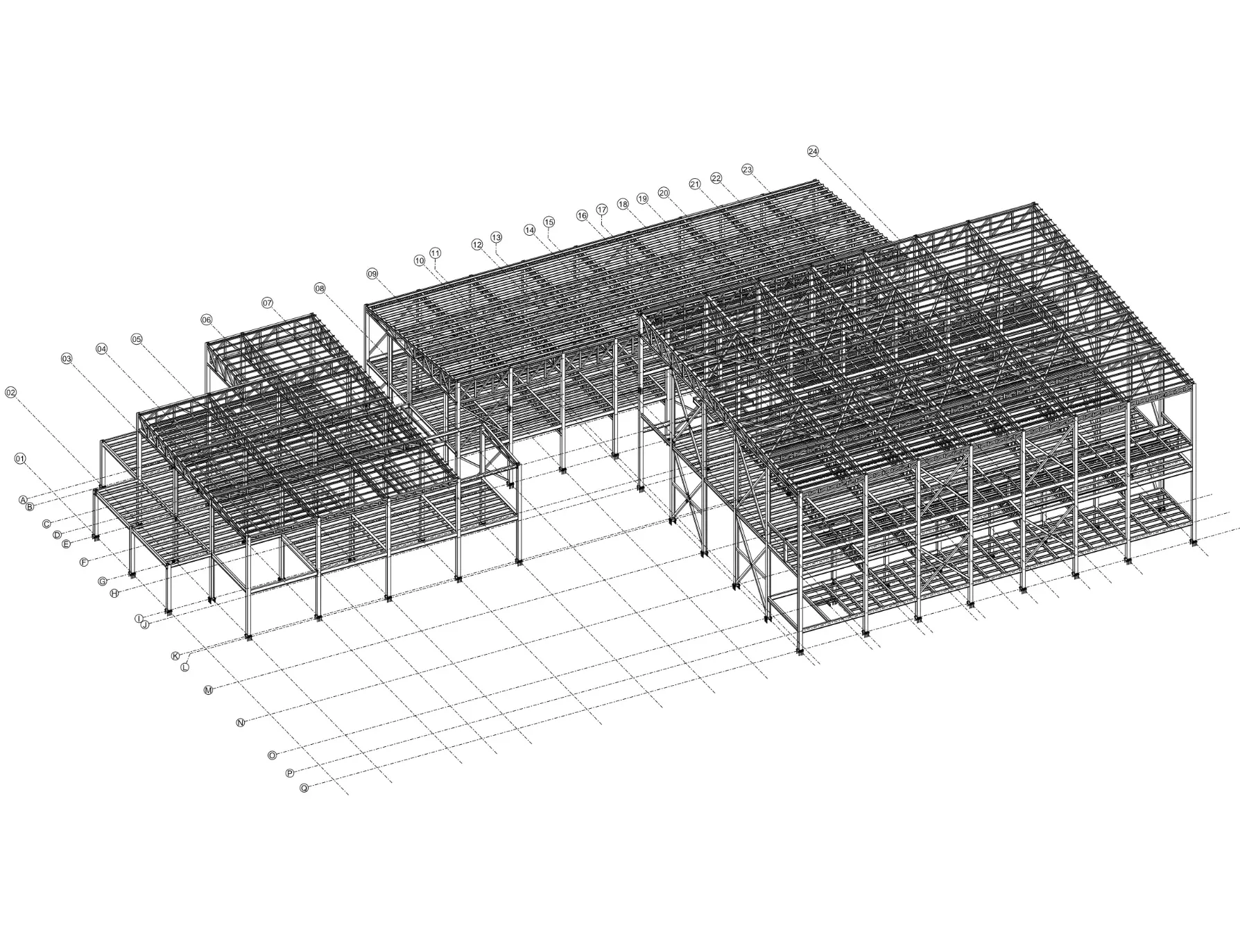
What are shop drawings? They are the drawings a fabricator uses to make and install each piece of a structure. The engineer’s design drawings say what the structure is: the frame layout, member sizes and typical connections. Shop drawings say exactly how every piece is made: every cut, hole, plate, weld and bolt, with a mark that tells the workshop and the site team which piece goes where.
The term is used in many trades (joinery, glazing, MEP, precast), but this guide covers structural steel, where the shop drawing package is the link between the approved design and the steel that arrives on site.
Design drawings vs shop drawings
| Design drawings | Shop drawings | |
|---|---|---|
| Prepared by | The structural engineer of record | The steel detailer, for the fabricator |
| Purpose | Show the structural system and design intent | Tell the workshop how to make each piece, and the site how to erect it |
| Content | Grids, member sizes, loads, typical connections, notes and specifications | Every assembly and part with exact dimensions, holes, welds, marks and quantities |
| Connections | Typical details, or connection forces for others to design | Every connection fully detailed |
| Used for | Approvals and tender | Purchasing, fabrication, painting, dispatch and erection |
A fabricator cannot build from design drawings alone. A design drawing may show a beam as “IPE 400, moment connection, see typical detail 5”. The shop drawing shows that beam’s exact cut length, the end plate size and thickness, the hole positions and diameters, the weld sizes, the stiffeners, the mark B-104 and that six of them are needed.
The shop drawing package
A complete steel shop drawing package has several types of drawing, each for a different reader.
Anchor bolt plans
The first drawings issued, often before the steel itself is approved, because the civil contractor needs them to cast the foundations. They show:
- the position of every anchor bolt group from the grids;
- the anchor bolt diameter, length, grade and projection above concrete;
- the top-of-concrete and grout levels;
- the base plate marks and setting-out details.
Errors here are the most expensive in the whole package: a wrongly placed cast-in bolt means coring, chemical anchors or a modified base plate later.
Erection drawings (general arrangement drawings)
Erection drawings, also called GA or marking drawings, are for the site team. They show the structure in plans, elevations and sections, with:
- the assembly mark of every member at its position;
- grids, levels and setting-out dimensions;
- the orientation of members where it matters, with the mark placed on a specific end or face;
- site bolt grades and sizes, and the connections to be site welded;
- notes on the erection sequence, temporary bracing and tolerances where the design calls for them.
The erector does not need to know how a beam was made; they need to know which beam goes where, which way round, and how it is connected.
Assembly drawings
Assembly drawings are the main workshop drawings. Each one shows one shipping piece (an assembly): a main part, such as a column or beam, with everything welded or bolted to it in the shop: end plates, cleats, stiffeners, base plates, gussets and shear studs. An assembly drawing shows:
- views and sections of the assembly, with all dimensions to holes, plates and ends;
- hole diameters and positions, with slotted holes where needed for erection tolerance;
- weld symbols, to AWS A2.4 or ISO 2553 depending on the project standard;
- a part list: each part mark, its profile, grade, length and quantity;
- the quantity of identical assemblies, the assembly weight and the surface finish (painting system or galvanising).
Single-part drawings
Single-part drawings show loose parts that are cut and drilled before assembly: plates, cleats, stiffeners, flats and angles. They give the part shape, thickness, grade, holes and bevels, so each part can be cut once and used in every assembly that needs it. On projects with CNC cutting, the same information goes to the machines as NC or DXF files, and the part drawing is the check for the workshop.
Other drawings in the package
Depending on the project, the package also includes:
- Embed plate drawings for plates cast into concrete, issued early like the anchor bolts.
- Bent and curved member drawings with the bending radius and the setting-out of the curve.
- Templates for anchor bolts and complex site connections.
- Stair and handrail drawings, often detailed as their own package.
Marking and numbering
Every assembly and part gets a mark, and identical pieces get the same mark. This is what lets the workshop make six identical beams as one batch, and the site team find the right beam in a pile of forty.
- Assembly marks usually start with a prefix for the member type, for example C for columns, B for beams, BR for bracing, P for purlins, followed by a number: C-12, B-104.
- Part marks follow a separate series, for example p1001 for a plate.
- Phases or zones split a large project into fabrication and erection batches, so the workshop makes the steel in the order it is erected.
Two pieces that look identical but differ by one hole are not identical, and must have different marks. A good numbering scheme, checked before issue, saves the site team from fitting the wrong piece.
Fabrication reports
Drawings are only half of the package. The reports, produced from the same model, are what purchasing, the workshop, the paint shop and the logistics team work from. The usual reports:
- Material list (bill of materials): total length and weight of each profile and plate thickness, by steel grade, for purchasing the steel.
- Assembly list: every assembly mark with its quantity, main profile, length, weight and surface area. Used to plan fabrication and to track progress.
- Part list: every part with its profile, grade, length, quantity and the assemblies it belongs to. Used for cutting.
- Bolt list: the bolts by diameter, length, grade, washers and nuts, split into shop bolts and site bolts, so the right boxes reach the right place.
- Anchor bolt list: anchor bolts, nuts, washers and plates for the civil contractor.
- Drawing register: every drawing with its title, current revision and status.
- Surface area report: painted area by assembly or by phase, used to price and order painting, fire protection or galvanising.
- Dispatch (shipping) list: assemblies grouped by delivery load or erection phase, with weights, for transport and site receipt.
- Weld list, on projects that need weld quantities or inspection planning.
- Nesting reports for plates, showing how parts are cut from stock sheets and the offcut loss.
Because all of these come from one model, they agree with each other and with the drawings. A report edited by hand after the model changed is one of the most common sources of shortages on site. For how the tonnage in these reports is built up, see our guide to steel weight calculation.
Machine files: NC and DXF
Modern workshops cut, drill and mark steel on CNC lines. The detailing model exports NC files (DSTV format) for beam lines and DXF files for plate cutting. The machine files must come from the same model revision as the approved drawings; mixing a new drawing with an old NC file is how holes end up in the wrong place.
The approval process
Shop drawings are reviewed by the consultant before fabrication. A typical sequence on UAE projects:
- Issued for approval (IFA). The detailer issues the drawings, usually starting with anchor bolts and then the main steel by zone.
- Review and status code. The consultant returns each drawing with a status. Codes vary by consultant, but a common set is: A, approved; B, approved with comments, proceed and incorporate them; C, revise and resubmit; D, rejected.
- Revision. Comments are incorporated, changes are clouded on the drawing, and the revision letter or number goes up.
- Issued for construction or fabrication (IFC). Only drawings at this status go to the workshop.
The consultant’s review checks that the shop drawings follow the design. It does not move the responsibility for dimensions and fit-up from the fabricator to the consultant, which is why the detailer’s own checking before issue matters.
Practical details that are easy to miss
Most problems found on site start as something that was not shown on a shop drawing:
- Vent and drain holes for galvanising. Hollow sections and closed boxes need holes so the zinc can flow in and out, and so trapped air does not cause an explosion in the bath. They must be on the drawings, in positions agreed with the galvaniser and the engineer.
- Transport size. Long or wide assemblies must fit on a trailer and through the site access. Site splices are placed where the design allows them, not where the trailer happens to end.
- Bolt access. Every bolt must have room for a wrench or tightening tool. The model shows it; a 2D drawing often hides it.
- Erection tolerance. Slotted holes, shims and packers where the design allows them, especially where new steel meets existing concrete.
- Lifting points and erection aids. Lifting lugs, erection cleats and temporary seats, shown and marked for removal where needed.
- Camber. Long beams with a specified camber need it shown on the assembly drawing, with the direction marked.
- Shop vs site welds. Site welding is slower and harder to inspect, so connections are planned to be welded in the shop and bolted on site wherever possible.
- Interfaces. Holes and cleats for cladding, MEP supports, handrails and other trades are far cheaper in the shop than drilled on site.
Shop drawings in Wrenze projects
On the Esaad building for Dubai Police, our scope covered structural design and detailing, so the same team that designed the curved entrance arch also set out its geometry and connections on the shop drawings. At the Al Jazirat Al Hamra Heritage Village, where the steel is exposed, the connections were detailed by the engineers who designed them, so they work and look neat. On the 30 m helical staircase in Dubai Airport Freezone, the 3D model fixed the geometry of every flight, landing and connection, which is the starting point for drawings of a structure where almost every member sits at an angle.
Shop drawing questions
Who prepares shop drawings?
The steel detailer, working for the fabricator or the steel contractor. The structural engineer prepares the design drawings, and the consultant reviews the shop drawings against them.
What is the difference between erection drawings and assembly drawings?
Erection drawings show where each assembly goes on site, with marks, grids and levels. Assembly drawings show how each assembly is made in the workshop, with every dimension, hole and weld.
What software is used for steel shop drawings?
Tekla Structures and Advance Steel are the most common. Both produce the drawings, reports and NC files from one 3D model.
How long do shop drawings take?
It depends on the size and complexity of the structure and on how complete the design is. Anchor bolt plans are normally issued first, so foundation work can continue while the main steel is detailed.
Related
Steel shop drawings and detailing · Steel connection design · Types of steel connections · Steel weight calculation
For shop drawings on your project, contact our engineers.