
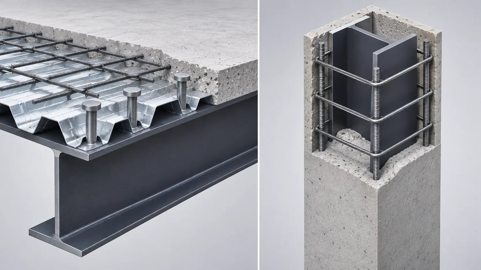
A shear stud is a headed steel pin welded to the top flange of a steel beam and cast into the concrete slab above it. The studs tie the slab to the beam so the two bend together as one composite section, with the concrete in compression and the steel mostly in tension. That composite action typically raises the bending capacity of a floor beam by 50 to 100% and its stiffness by two to three times, which is why almost every steel-framed floor with a concrete slab on metal deck is designed as composite.
This guide covers how shear studs work, how their capacity is calculated to AISC 360 and Eurocode 4, how metal deck reduces that capacity, how many studs a beam needs, the spacing and detailing rules, and how studs are welded and tested on site. A worked example for a typical office floor beam is at the end.
How shear studs work
When a beam and slab bend without any connection, each one bends about its own neutral axis, and the underside of the slab slides over the top of the beam. Shear studs stop that slip. They carry the longitudinal shear between the slab and the beam, the horizontal force that builds up from zero at the support to its maximum at the point of maximum moment.
The total force the studs must transfer between a support and the point of maximum moment is the smaller of:
- The steel beam yielding in tension: As × Fy
- The concrete slab crushing in compression: 0.85 f′c × Ac, where Ac is the effective slab width times the concrete thickness above the deck
If the studs can carry this full force, the beam has full shear connection and reaches its full plastic composite moment. If they carry less, the beam has partial shear connection. Its moment capacity then depends on the force the studs can actually deliver. Partial connection is normal and economical, within the limits given below.
Headed studs are ductile. Under overload they bend and slip without breaking, so the studs along a beam share the longitudinal shear evenly. That is why the studs between a support and the point of maximum moment can be spaced uniformly rather than following the shear diagram.
The headed stud
The most common shear stud in steel buildings is 19 mm in diameter (¾ in), with 16 mm and 22 mm used less often. Typical lengths after welding are 95 to 125 mm, chosen so the stud reaches well into the slab above the deck ribs.
- Material: low-carbon steel with a minimum tensile strength Fu of 450 MPa (65 ksi), to AWS D1.1 Type B or EN ISO 13918 SD1
- Head: about 32 mm diameter for a 19 mm stud. The head resists uplift and anchors the stud in the concrete
- Weld: arc stud welded with a ceramic ferrule that shapes the weld fillet around the base. The weld is made in under a second with a stud welding gun and a high-current power supply
Shear stud capacity to AISC 360
AISC 360 Section I8.2a gives the nominal strength of one headed stud in a composite beam as:
Qn = 0.5 Asa √(f′c Ec) ≤ Rg Rp Asa Fu
where Asa is the stud shank area, f′c the concrete compressive strength, Ec the concrete modulus, and Fu the stud tensile strength. The first term is the concrete failing around the stud; the second is the stud itself failing in shear, reduced by two factors:
- Rg for the number of studs in a deck rib and the rib geometry
- Rp for the position of the stud in the rib
For a 19 mm stud (Asa = 283.5 mm²) in normal-weight concrete with f′c = 30 MPa (Ec ≈ 27,700 MPa):
- Concrete limit: 0.5 × 283.5 × √(30 × 27,700) ≈ 129 kN
- Stud limit with Rg = 1.0 and Rp = 0.75: 0.75 × 283.5 × 450 ≈ 95.7 kN
So the stud limit governs, and the capacity depends mainly on the deck:
| Slab and stud arrangement | Rg | Rp | Qn per 19 mm stud |
|---|---|---|---|
| Solid slab, no deck | 1.0 | 0.75 | 95.7 kN |
| Deck ribs parallel to the beam (wide ribs) | 1.0 | 0.75 | 95.7 kN |
| Deck ribs perpendicular, 1 stud per rib, strong position | 1.0 | 0.75 | 95.7 kN |
| Deck ribs perpendicular, 1 stud per rib, weak position | 1.0 | 0.60 | 76.6 kN |
| Deck ribs perpendicular, 2 studs per rib, weak position | 0.85 | 0.60 | 65.1 kN each |
| Deck ribs perpendicular, 3 studs per rib, weak position | 0.70 | 0.60 | 53.6 kN each |
The strong and weak positions refer to where the stud sits in the rib. Many deck profiles have a stiffener in the middle of the rib, so the stud has to go to one side. On the side nearer the support the concrete in front of the stud is thin, which is the weak position. AISC 360 uses Rp = 0.75 only when the distance from the stud to the mid-height of the rib wall, in the direction of the shear, is at least 51 mm. Unless the shop drawings and site control fix the strong position, designers usually assume the weak one.
Shear stud capacity to Eurocode 4
EN 1994-1-1 gives the design resistance of a headed stud as the smaller of:
- Stud failure: PRd = 0.8 fu π d² / 4 / γv
- Concrete failure: PRd = 0.29 α d² √(fck Ecm) / γv
with γv = 1.25 and α = 1.0 when the stud height is at least 4 times its diameter. For a 19 mm stud with fu = 450 MPa in C30/37 concrete (Ecm = 33 GPa):
- Stud: 0.8 × 450 × 283.5 / 1.25 ≈ 81.7 kN
- Concrete: 0.29 × 1.0 × 19² × √(30 × 33,000) / 1.25 ≈ 83.3 kN
For deck ribs perpendicular to the beam, this is multiplied by a reduction factor kt that depends on the rib width b0, the rib height hp, the stud height hsc and the number of studs per rib nr:
kt = (0.7 / √nr) × (b0 / hp) × (hsc / hp − 1)
kt is capped at an upper limit that depends on the deck thickness and whether the studs are welded through the deck. For one stud per rib welded through deck up to 1.0 mm thick, the cap is 0.85. On common 50 to 60 mm decks this cap often governs, giving about 0.85 × 81.7 ≈ 69 kN per stud.
The two codes give similar answers once their different safety formats are allowed for. What matters on a project is using one code consistently for the beam, the studs and the slab.
Full and partial shear connection
The degree of shear connection is the force the studs can deliver, ΣQn, divided by the force needed for full connection, the smaller of As Fy and 0.85 f′c Ac.
On metal deck there is only one rib every 150 to 300 mm, and often only one stud fits in each rib. That usually limits the degree of shear connection, so most floor beams on deck are designed with partial connection, typically 40 to 80%.
There are lower limits:
- AISC 360: the Commentary recommends at least 25% shear connection. Very low degrees of connection give little benefit and can lead to large slip and deflection.
- Eurocode 4: for beams with equal flanges up to 25 m span, the minimum degree is η ≥ 1 − (355 / fy)(0.75 − 0.03 Le), and not less than 0.4, where Le is the span in metres. For an S355 beam spanning 9 m this gives 0.52.
The Eurocode limit rises as the span gets shorter, because in short beams the slip at low degrees of connection would exceed the deformation capacity of the studs.
How many studs a beam needs
For a simply supported beam under uniform load, the number of studs needed between each support and midspan is:
n = (required force) / Qn
with the required force taken for the degree of connection chosen in the design. The same number is placed in the other half of the span. Point loads from secondary beams need studs arranged so that enough connection is provided between each point load and the nearest support.
For beams with ribs perpendicular to the beam, the studs are placed in the ribs, so the number per half span is limited to the number of ribs times the studs per rib. For ribs parallel to the beam, studs can be placed at any spacing along the trough, subject to the spacing rules.
Spacing and detailing rules
The main detailing rules in AISC 360 Section I8.2d and I3.2c are:
- Stud diameter: not more than 2.5 times the flange thickness, unless the stud is placed directly over the web
- Length: at least 4 stud diameters after welding, and at least 38 mm (1½ in) above the top of the deck
- Cover: at least 13 mm (½ in) of concrete above the top of the stud head
- Minimum spacing: 6 diameters along the beam and 4 diameters across it, or 4 diameters in any direction within deck ribs perpendicular to the beam
- Maximum spacing: 8 times the total slab thickness, and not more than 900 mm (36 in)
- Deck limits for composite design: rib height not more than 75 mm (3 in), average rib width at least 50 mm (2 in), and at least 50 mm (2 in) of concrete above the deck
- Deck anchorage: where studs are not at every rib, the deck is anchored to the beam at not more than 460 mm (18 in) centres by welds, studs or other fixings
Eurocode 4 has equivalent rules, including an edge distance from the stud to the flange edge of at least 20 mm and a stud height at least 2 diameters above the top of the deck.
The construction stage
A composite beam is only composite once the concrete has hardened. Before that, an unpropped beam carries the wet concrete, the deck, its own weight and construction loads as a bare steel beam. The construction stage checks are:
- Strength of the bare steel beam, with the deck restraining the top flange laterally once it is fixed down
- Deflection under wet concrete. This sets the extra concrete added by ponding, and whether the beam is precambered.
- Construction loads for workers, equipment and concrete heaping, to ASCE 37 or EN 1991-1-6
Propping the beams avoids the construction stage limits but costs programme and temporary works. Most UAE projects use unpropped composite beams and design the beam for both stages.
Welding, testing and site problems
Studs are welded either directly to the beam flange before the deck is laid, or through the deck onto the flange after it is laid. Through-deck welding fixes the deck and places each stud in its rib in one step. It works on galvanised deck up to about 1.25 mm thick with standard zinc coatings, provided the deck is dry and in tight contact with the flange.
Common problems on site, and how the specification prevents them:
- Paint or intumescent on the top flange. Studs cannot be welded through primer or fire protection, so the top flange is masked or left unpainted over the stud zone. See our guide to intumescent paint for how the rest of the beam is protected.
- Wet or contaminated deck, which causes porosity and weak welds. Welding stops in rain and the deck is dried first.
- Gaps between deck and flange, from uneven flanges or poor fixing, which give poor through-deck welds
- Wrong stud position in ribs with a central stiffener, turning strong positions into weak ones
Quality control to AWS D1.1 starts with pre-production tests at the start of each shift or after any change in setup. Studs are bent about 30° from vertical and must not crack in the weld. During production, studs are checked visually for a full 360° weld collar, and studs with a defective collar are bend-tested. Studs that fail are replaced. Bent studs that pass can usually stay in place where the specification allows.
Worked example: an office floor beam
A secondary beam in an office floor in Dubai:
- Span 9.0 m, simply supported, beams at 3.0 m centres
- Slab 130 mm overall on 51 mm deck, ribs at 300 mm, perpendicular to the beam
- Normal-weight concrete f′c = 30 MPa, steel S355 (Fy = 355 MPa)
- Loads: slab 2.6 kPa, finishes and services 1.5 kPa, live load including partitions 4.0 kPa
- Factored load to ASCE 7: wu = 1.2 × (4.1 × 3.0 + 0.45) + 1.6 × (4.0 × 3.0) ≈ 34.5 kN/m
- Required moment: Mu = wu L² / 8 ≈ 350 kNm
Bare steel. The beam would need a plastic modulus of 350 × 10⁶ / (0.9 × 355) ≈ 1,100 cm³, which means a UB 406×178×60 (60 kg/m).
Composite. Try UB 356×171×45 (45 kg/m, A = 57.3 cm², Zx = 775 cm³).
- Effective slab width: 2 × min(L/8, s/2) = 2 × 1.125 = 2.25 m
- Full connection force: As Fy = 5,730 × 355 ≈ 2,034 kN, against 0.85 × 30 × 2,250 × 79 ≈ 4,533 kN for the concrete above the deck. Steel governs at 2,034 kN.
- Ribs per half span: 4,500 / 300 = 15. With one stud per rib in the weak position, ΣQn = 15 × 76.6 ≈ 1,149 kN.
- Degree of connection: 1,149 / 2,034 ≈ 56%. That is above the AISC minimum of 25%, and also above the Eurocode minimum of 52% for this span.
With partial connection, the concrete compression block depth is a = 1,149,000 / (0.85 × 30 × 2,250) ≈ 20 mm. The remaining steel compression, (2,034 − 1,149) / 2 ≈ 443 kN, fits in the top flange. Taking moments of the concrete force, the steel compression and the steel tension gives Mn ≈ 492 kNm.
φMn = 0.9 × 492 ≈ 443 kNm > Mu = 350 kNm, a ratio of 0.79.
Construction stage:
- Strength: the bare UB 356×171×45 carries the wet concrete and construction load (Mu ≈ 149 kNm) against φMp ≈ 248 kNm.
- Deflection: under the wet concrete it deflects about 29 mm, span/308. That is acceptable with an allowance for ponding, or the beam can be precambered by about 25 mm.
Result. The composite UB 356×171×45 with 30 shear studs replaces a bare UB 406×178×60, saving 15 kg/m, a quarter of the beam weight. The beam is also shallower and much stiffer for floor vibration. Repeated over a floor plate, this is where composite design saves steel tonnage. Live-load deflection and floor vibration are then checked on the composite section, with long-term effects for the concrete.
Shear studs in our projects
Composite floors with shear studs are part of most multi-storey steel buildings we design.
- Tramontina warehouse and offices, Dubai Industrial City: the office mezzanine is framed with steel beams and a concrete slab on metal deck, acting compositely through shear connectors to reduce beam depth and increase stiffness.
- MBF headquarters office: composite action with the floor slab is used where it reduces depth and increases stiffness on the long-span floors.
- Electra by Acube Developments, Dubai: composite columns and composite shear walls.
See our composite steel design and mezzanine floor design services.
Shear stud questions
What size are shear studs?
The most common size is 19 mm diameter, 95 to 125 mm long after welding, with 16 mm and 22 mm also used. The length is chosen so the stud projects at least 38 mm above the top of the deck and keeps at least 13 mm of concrete cover over its head.
What is the capacity of a 19 mm shear stud?
In 30 MPa normal-weight concrete it is about 96 kN nominal to AISC 360 in a solid slab or a strong deck position. That drops to about 77 kN in the weak position and about 65 kN each with two studs per rib. To Eurocode 4 the design resistance is about 82 kN in a solid slab, reduced by the factor kt for transverse deck ribs.
Can shear studs be welded through metal deck?
Yes. Through-deck welding is standard for galvanised deck up to about 1.25 mm thick, provided the deck is dry, clean and tight against the beam flange, and the flange is unpainted where the studs are welded.
How are shear studs tested?
To AWS D1.1, test studs are bent about 30° at the start of each shift and after any change in setup, and must not crack. Production studs are checked visually for a full weld collar, and doubtful studs are bend-tested or replaced.
Do composite beams always need full shear connection?
No. Most beams on metal deck use partial shear connection, typically 40 to 80%, because the number of deck ribs limits the number of studs. The design checks the moment capacity for the connection actually provided, and keeps it above the code minimum.
Related
Composite steel design · Mezzanine floor design · Structural steel design · Intumescent paint for structural steel · Cold-formed and light gauge steel design
For composite floor design on your project, contact our engineers.