Wrenze Steel provides gusset plate design services and bracing connection design for real estate developers, architects and engineering consultancies, contractors and steel fabricators in Dubai, across the UAE and in the GCC. Bracing gives a steel frame its stability against wind and earthquake, and every brace force passes through a gusset plate or an end connection before it reaches the beams, the columns and the foundations. A bracing connection that is too weak, too flexible or badly placed can undo a well-designed frame. We design gussets and brace ends that carry the full forces, match the analysis model and are simple to fabricate and erect.
Bracing connections we design
- Corner gussets: gusset plates at the beam-column junction, connected to both members, for vertical bracing in buildings, warehouses and pavilions
- Mid-span gussets: gussets at the beam for chevron (V and inverted V) bracing, with checks of the beam web and flange under the concentrated forces
- Bolted brace ends: angles, double angles, channels and tee sections bolted to the gusset
- Welded brace ends: braces fillet-welded to the gusset in the shop, with a bolted site connection elsewhere
- Slotted hollow section ends: square, rectangular or round hollow section braces slotted over a gusset plate, or fitted with a welded end plate or knife plate
- Tension-only rod bracing: round bars with threaded ends, turnbuckles, clevises or eye plates, common in roof and wall bracing
- X-brace crossings: one diagonal continuous and the other connected through a plate at the crossing
- Roof and plan bracing: gussets and cleats that tie roof bracing to rafters, trusses and purlins
For how bracing systems are chosen in the first place, see our guide to bracing in steel structures.
Gusset plate design checks
Whitmore section and block shear
The brace force enters the gusset through bolts or welds and spreads into the plate. We take the Whitmore width, with the force spreading at 30 degrees from the first bolt row to the last, and check yielding and net section fracture across it. Block shear is checked around the bolt group or weld outline on the gusset and on the brace itself, to AISC 360 Chapter J. Bolt bearing and tearout, shear lag in the brace and the net area at the end of any slot complete the tension checks.
Compression and buckling of the free edge
Under compression the gusset can buckle. We check the Whitmore section as a column, with an effective length taken from the unbraced length of the plate between the end of the brace and the beam or column, following the AISC design guide for vertical bracing connections. Long unsupported free edges are checked separately; where an edge is too slender, the plate is thickened or an edge stiffener is added along it.
Uniform force method for corner gussets
A corner gusset delivers the brace force to two members at once. We use the uniform force method to share it between the gusset-to-beam and gusset-to-column interfaces, choosing the gusset geometry so that, where possible, neither interface carries a moment. The interface forces then go into the weld or bolt design, the beam web, the column flange or web and the beam-to-column connection, which carries part of the brace force as well as its own shear. Where the gusset shape is fixed by the architecture or the services, the special cases of the method account for the moments.
Eccentricity and work points
Brace centrelines are normally set to meet at a single work point, at the intersection of the beam and column centrelines. When the brace is moved off that point to clear a door, a duct or a cladding line, the eccentricity produces moments in the beam and column. We either detail the joint back to a common work point or design the members and connections for the moment. Weld groups and bolt groups are also checked for any eccentricity between the brace line and the connector centroid.
Seismic bracing and the 2t clearance
Many UAE buildings use ordinary concentrically braced frames, with connections designed for the analysis forces. Where the seismic design calls for a special concentrically braced frame under AISC 341, the connection is designed for the expected strength of the brace in tension and compression, not the analysis force. For braces that buckle out of plane, the gusset is detailed with a clear fold line of twice its thickness, the 2t clearance, between the end of the brace and the restrained edge, so the plate bends without fracture. An elliptical clearance or a different fold line is used where the geometry suits it better.
Brace end connections
Bolted and welded ends
Bolted angles and channels are quick to erect and easy to adjust on site. We check the bolts in shear and bearing, shear lag in the outstanding legs, and decide between bearing-type and slip-critical bolts, using slip-critical where the force reverses and slip would loosen the frame. Welded ends suit heavier braces and shop assembly, with weld lengths set for the shear lag factor in the brace.
Hollow section braces
A hollow section brace slotted over a gusset is a clean detail, but the slot reduces the net area at the end of the brace. We check shear lag along the weld length and, where the net section governs, add reinforcing plates or use a capped end with a knife plate. See our page on hollow section connection design.
Rod bracing and turnbuckles
Tension-only rods are checked on the threaded area at the ends, with the turnbuckle, clevis or nut sized to develop the rod. The rod is connected to the frame through a cleat, an eye plate or a hole in the web, and that part is checked for the rod force and its angle. Because rods carry no compression, the frame model includes them in tension only, with the opposite diagonal taking the load when the wind reverses.
X-brace crossings
At a crossing, one diagonal runs through and the other is connected to it with a plate. When the tension diagonal is strong and stiff enough, the crossing acts as a brace point for the compression diagonal, halving its buckling length out of plane. We design the crossing plate and its bolts for that role, and check the gap and the packing so the two diagonals sit in line.
Codes
We design bracing connections and gusset plates to AISC 360, with the AISC Steel Construction Manual and design guide for vertical bracing connections, AISC 341 where seismic detailing applies, AWS D1.1 for welding, and ASCE 7-16 for loads, together with the requirements of Dubai Municipality or the authority for the project’s emirate. The Eurocodes or British Standards are used where the project specification requires.
What you receive
- A calculation report for each bracing connection type, with brace forces, the governing combination and every check
- Gusset plate sketches with plate shape and thickness, work points, bolt and weld sizes, slot lengths and clearances
- Interface forces to the beams, columns and base plates, with the beam-to-column connection checks where the brace force passes through them
- Rod, turnbuckle and cleat details for tension-only bracing
- Responses to the consultant’s comments until the connections are approved
Gusset plate design services: how a project runs
- You send the design drawings, the brace forces or the analysis model, and the specification.
- We agree the design forces with the consultant, including any seismic requirements.
- We group the bracing connections into types and take the governing force for each.
- We design each type, set the gusset geometry and check the beams and columns at the joint.
- We issue the calculations and sketches for approval and answer the comments.
- Our detailing team can take the approved connections into the 3D detailing model.
Bracing connection projects
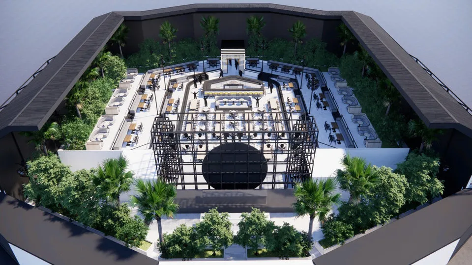
At the Acoustic Hall in Festival City, a U-shaped steel hall designed for Impart Design Group, a continuous roof bracing system ties the trussed frames together around the whole plan and delivers wind and seismic loads to braced bays in the walls, arranged around doors and plant zones. Our connection design covered the bracing nodes along with the truss nodes, splices and moment connections.
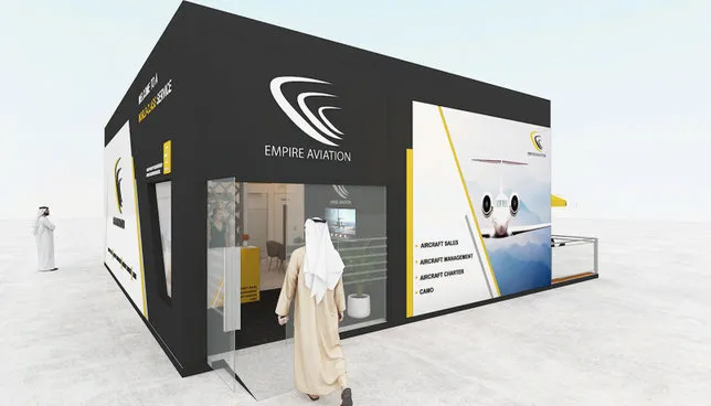
For the Empire Aviation pavilion at the Dubai Airshow, X-bracing in the roof plane acts as a diaphragm and feeds braced bays in the walls, set behind solid panels to keep the glazing clear. The bracing connections were bolted for fast assembly and dismantling.
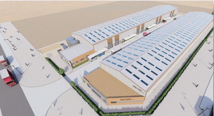
On the DIC Warehouses in Dubai Industrial City, roof bracing and vertical wall bracing carry the gable wind along each building, with bracing bays placed clear of the loading doors, and the bracing connections designed with the haunched frame connections and base plates.
Why choose a specialist gusset plate design consultant
- Our engineers hold Dubai Municipality practice certificates, and we prepare Dubai Municipality submissions through to approval.
- A steel structure design consultancy: bracing connections are designed by the same team that designs the frame, so the forces and work points match the analysis.
- 96 projects completed across the UAE and the GCC.
- Our office is in Dubai Silicon Oasis, and we work across the UAE and the GCC.
Related pages
Steel connection design · Steel moment connection design · Base plate and anchor bolt design · Bracing in steel structures · All steel connection types
For gusset plate and bracing connection design, contact our engineers.