Wrenze Steel is a finite element connection design consultant in Dubai, working across the UAE and the GCC for real estate developers, architects and engineering consultancies, contractors and steel fabricators. Finite element connection design is the analysis of a steel joint as a model of its plates, bolts and welds, used where hand methods cannot follow the load path with confidence. Most connections in a building follow standard methods. The difficult ones are the joints with many members, unusual angles, heavy stiffening or architectural shapes, and they are often the most heavily loaded points in the structure. For these, we model the connection itself, check every part against the code, and validate the model against hand calculation.
When finite element connection design is used
- Non-standard geometry: members arriving skewed, sloped or in three dimensions, as in curved roofs, folded canopies and feature structures
- Many members at one node: truss nodes, gridshell and space frame hubs, branching columns and cable anchorages
- Stiffener layouts: column panel zones, haunches and base plates where stiffeners are added, removed or rearranged to save fabrication
- Plates with openings or cut-outs: joints where services, architecture or bolting access remove part of a plate
- Hollow section joints outside the code limits: branches at small angles, thin chords or multiplanar joints; see hollow section connection design
- Existing connections: joints in existing steel that carry new loads, where strengthening is checked before it is detailed
- Economy: heavily repeated connections, where a more precise check removes plate thickness or stiffeners across hundreds of joints
How the finite element model is built
Plates, bolts and welds
The plates are modelled as shell elements with an elastic-plastic steel material, so the model shows where the steel yields and how the forces redistribute. Bolts are modelled as components that carry tension, shear and bearing, with contact between plates so prying forces develop as they do in the real joint. Welds are modelled along their real lengths and throats, and anchors are modelled into a concrete block where the connection reaches the foundation.
Loads from the global analysis
The connection is loaded with the forces from the global analysis model, combination by combination. We use consistent sets of forces from the same combination for every member at the node, because taking the maximum of each force separately can produce a load case that never happens and miss the one that governs. Members are modelled long enough that the boundary does not disturb the stresses at the joint.
Finite element connection design checks
Plate stresses and plastic strain
Plates are checked for equivalent plastic strain against a limit of 5 percent, the limit widely used for structural steel in finite element design. Small local yielding at bolt holes and plate corners is accepted, as in hand methods; spreading yield across a plate is not. We review the strain plot as well as the peak value, because a pattern of yielding shows a weak load path that a single number can hide.
Bolt and weld checks
Bolt forces from the model, including prying, are checked to AISC 360 for tension, shear, combined tension and shear, bearing and tearout, and slip resistance where bolts are slip-critical. Weld stresses are checked to AISC 360 with the directional strength of fillet welds, and full penetration welds are checked against the base metal. Anchor forces go into the concrete checks of ACI 318 Chapter 17, as on our base plate and anchor bolt design page.
Buckling of plates
A plastic analysis does not show buckling on its own. We run a buckling analysis of the connection to find the critical load factor. Where it is low, the plate is checked by the code methods for gussets and stiffeners, or the model is rerun with geometric nonlinearity and imperfections. Free edges of gussets and slender stiffeners are the usual places where buckling governs.
Stiffness classification
The model gives the moment-rotation curve of the joint. We classify it as rigid, semi-rigid or pinned using the AISC 360 stiffness criteria, and compare it with the assumption in the frame analysis. A joint modelled as rigid that turns out semi-rigid changes the moments, the drift and the buckling lengths of the frame, so the frame is re-analysed with the real stiffness or the connection is stiffened to match. The same check applies to the moment connections of portal frames and multi-storey frames.
Validation against AISC hand checks
A finite element model is only as good as its set-up, so every model type is validated. We compare the results with AISC hand checks on a comparable standard joint: an end plate with prying, a Whitmore section, a stiffened column web. We refine the mesh until the results settle, confirm that reactions balance the applied forces, and check the deformed shape for sense. Capacity design forces for seismic connections, fatigue and the overall buckling of members are checked separately by the code methods, and the report states which checks come from the model and which by hand.
Codes
Connections are checked to AISC 360, with AISC 341 where seismic detailing applies, AWS D1.1 for welding, ACI 318 Chapter 17 for anchors and ASCE 7-16 for loads, together with the requirements of Dubai Municipality or the authority for the project’s emirate. The Eurocodes or British Standards are used where the project specification requires.
What you receive
- A calculation report for each connection type: geometry, materials, load combinations, stress and plastic strain plots, bolt, weld and anchor checks
- Buckling factors and stiffness classification for each joint where they matter
- Validation hand checks next to the finite element results
- Connection sketches with every plate, bolt, weld and stiffener
- Responses to the consultant’s comments until the connections are approved
Finite element connection design services: how a project runs
- You send the drawings, the analysis model or member forces, and the specification.
- We identify the joints that need finite element analysis and design the standard joints by hand.
- We build the connection models, apply the governing combinations and check every part.
- We adjust plates and stiffeners for economy and fabrication, and confirm the stiffness against the frame.
- We issue the calculations and sketches for approval and answer the comments.
Finite element connection projects
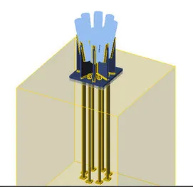
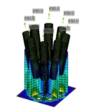
At Expo 2020 Dubai, for the Brazil Pavilion with MJU Engineering Consultancy as consultant, several cable fittings meet at each anchorage, each designed for a tension of 650 kN and arriving at its own angle. Our engineers modelled the radial gussets, stiffeners, the 40 mm base plate, the welds and the bolts, with the forces applied along each cable axis, checked stress, strain and deformation across every plate and weld, and took the bolt forces into the anchorage design.
For a gridshell in Dubai Media City, each node joins several members arriving in three dimensions. Finite element models of the hub and its round end plates showed how stress flows through the node and where it concentrates, and confirmed the node stiffness assumed in the global model. Related work through detailed connection analysis includes the branching tree-column nodes of the Cafe Del Mar Island Bar and the vault nodes of the Open Market Building in Abu Dhabi.
Why choose specialist finite element connection design consultants
- Our engineers hold Dubai Municipality practice certificates, and we prepare Dubai Municipality submissions through to approval.
- A steel structure design consultancy: finite element connection analysis is part of our everyday connection design, used where it adds certainty or saves steel.
- 96 projects completed across the UAE and the GCC.
- Our office is in Dubai Silicon Oasis, and we work across the UAE and the GCC.
Related pages
Steel connection design · Steel moment connection design · Hollow section connection design · Gusset plate and bracing connections · All steel connection types
For finite element connection design, contact our engineers.