
Wrenze Steel is a hollow section connection design company in Dubai, working across the UAE and the GCC for real estate developers, architects and engineering consultancies, contractors and steel fabricators. Hollow section connection design is the design of joints between round, square and rectangular hollow sections, and between hollow sections and plates. Hollow sections give clean, efficient members for trusses, space frames, gridshells, canopies, feature columns and exposed structures. Their joints work differently from those of open sections: the force passes through a thin tube wall rather than a stiff flange, so the wall itself often decides the strength. We design these joints to carry the member forces with as few stiffeners and plates as the code allows, and to stay clean where the steel is on show.
Hollow section joints we design
- T and Y joints: a single branch meeting a chord at right angles or at an angle, as at truss verticals and inclined posts
- K and N joints: two branches on the same side of the chord, one in tension and one in compression, as in most Warren and Pratt trusses
- X joints: branches on opposite sides of the chord, as at crossings and where loads pass straight through a member
- KT and multiplanar joints: three or more branches, or branches in more than one plane, as in triangular trusses and space frames
- Plate-to-HSS connections: transverse plates, longitudinal shear plates, through-plates and knife plates for beams, braces and brackets
- End plates and flange splices: bolted end plates for round and rectangular hollow sections, used for splices and for site connections
- Nodes: fabricated hubs and plate nodes, and cast steel nodes, for space frames, gridshells and branching columns
For our wider design of tubular structures, see hollow section steel design.
Hollow section connection design checks
Joint geometry and validity limits
The strength of a hollow section joint depends on its proportions: the width or diameter ratio of branch to chord, the chord slenderness, the branch angles and, for K joints, the gap or overlap. AISC 360 Chapter K gives strength equations within set limits on each of these. We check the limits first. Where a joint falls outside them, we change the members, reinforce the joint or verify it through finite element connection design.
Chord face plastification
When a narrow branch pushes or pulls on a wide chord, the chord face bends like a plate and forms a yield mechanism around the branch footprint. This often governs T, Y and X joints with small branch-to-chord ratios. The chord strength is reduced where the chord itself is highly stressed, so the chord axial force and moment at the joint are part of the check.
Punching shear
A thin chord wall can shear through around the perimeter of the branch, as if the branch were punching out a piece of the wall. This is checked for branches narrower than the chord and limits how thin the chord wall can be relative to the branch.
Branch effective width and chord side walls
In rectangular sections the branch wall does not carry load evenly: the parts in line with the stiff chord side walls carry more than the middle. We check the branch for its effective width. Where the branch and chord are of similar width, the chord side walls take the load directly and are checked for local yielding and crippling.
Gap and overlap K joints
Gap joints are simpler to cut and weld, and the gap must be at least the sum of the branch wall thicknesses so each weld can be made properly. Overlap joints carry more force and are stiffer, with part of the force passing directly between the branches; they need a set welding sequence and a decision on whether the hidden toe is welded. The chord in the gap of a gap joint is checked for shear.
Welds
Welds around a branch change in angle as they run round the tube, from the toe to the heel and the sides. We design branch welds either to develop the branch or for the actual forces, using the effective lengths in AISC 360, and specify welds to the tubular provisions of AWS D1.1. Effective weld lengths are reduced where stiffness varies around the joint, so a weld sized by length alone can be unsafe.
End plates and through-plates
Bolted end plates on hollow sections are checked for plate bending and prying, with bolts on two or four sides depending on the force. A through-plate passes through slots in both walls of the section and spreads a beam or bracket force into both faces, much stronger than a plate welded to one face. Shear lag is checked where a slotted tube is welded to a gusset; see gusset plate and bracing connections.
Fatigue
Hollow section joints in signboards, crane structures, bridges and slender members excited by wind see repeated stress cycles. Where fatigue applies, we check the joints with the stress range method in AISC 360 Appendix 3, and choose details with smooth load paths and full penetration welds at the critical points.
Nodes for space frames and gridshells
On a space frame or gridshell, the nodes take most of the design effort. Many members meet at each node, at angles that change across the surface, each carrying axial force, shear and bending. We design the node family to cover the full range of angles and forces, so fabrication stays as repetitive as the geometry allows: fabricated hubs with end plates, plate nodes, or cast steel nodes where the shape or the forces call for them. Node stiffness is confirmed against the assumption in the global model, because the nodes control how the shell resists buckling. See our space frame and gridshell structure design work.
Codes
We design hollow section connections to AISC 360 Chapter K, with the AISC design guide for HSS connections, AWS D1.1 for tubular welds and ASCE 7-16 for loads, together with the requirements of Dubai Municipality or the authority for the project’s emirate. The Eurocodes or British Standards are used where the project specification requires.
What you receive
- A calculation report for each joint type, with the member forces, validity limits and every check
- Joint sketches with member sizes, gaps or overlaps, weld types and sizes, plates and bolts
- Node designs and finite element connection analysis where a joint is outside the code equations
- Sealing, vent and drain hole details for sealed and galvanised sections
- Responses to the consultant’s comments until the joints are approved
Hollow section connection design services: how a project runs
- You send the design drawings, the member forces or analysis model, and the specification.
- We check the joint geometry against the code limits and agree any member changes with the designer.
- We group the joints into types and design each type for its governing forces.
- We verify non-standard joints and nodes through finite element connection analysis.
- We issue the calculations and sketches for approval and answer the comments.
Hollow section and node projects
For the Cafe Del Mar Island Bar in Abu Dhabi, closed hollow sections and sealed, drained details were used to resist the marine environment. The connection design covered the radial-to-ring joints of the circular canopy, the canopy-to-column moment connections and the branching nodes of the tree-shaped columns, where each branch brings its share of the roof back to the trunk, through detailed connection analysis.
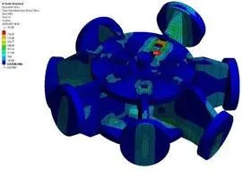
For a gridshell in Dubai Media City, for Summit Engineering Consultants, we designed the gridshell nodes: a central steel hub with round end plates on each incoming member. Each node type was checked for the forces from every member, with finite element models of the connection and its stiffness confirmed against the global model.
Why choose a specialist hollow section connection design consultant
- Our engineers hold Dubai Municipality practice certificates, and we prepare Dubai Municipality submissions through to approval.
- A steel structure design consultancy: hollow section joints and nodes are designed with the members, so the sections chosen in the frame also work at the joints.
- 96 projects completed across the UAE and the GCC.
- Our office is in Dubai Silicon Oasis, and we work across the UAE and the GCC.
Related pages
Hollow section steel design · Space frame and gridshell design · Steel connection design · Finite element connection design · All steel connection types
For hollow section connection design, contact our engineers.