Wrenze Steel provides steel splice design services for real estate developers, architects and engineering consultancies, contractors and steel fabricators in Dubai, across the UAE and in the GCC. Steel splice design sets where a long member is divided into pieces and how those pieces are joined again so the member works as one. Rafters, trusses, transfer beams, bridge girders and the columns of multi-storey buildings are usually longer or heavier than a single piece can be fabricated, transported or lifted, so splices are part of almost every steel structure. We design splices that carry the forces at their location, fall where they suit the fabricator and the erector, and keep site work short.
Splice types we design
- Bolted flange and web cover plates: plates on the flanges, inside and outside, and on both sides of the web, bolted across the joint. This is the usual splice for rolled beams, plate girders and columns.
- End plate splices: a plate welded to the end of each piece and bolted together on site, flush or extended. Common in portal frame rafters, apex joints and PEB frames.
- Welded splices: complete joint penetration groove welds across the flanges and web, made in the shop where possible, for full-strength or concealed joints.
- Column splices in bearing: column ends milled to bear, with flange and web plates holding the pieces in line and carrying tension, shear and moment.
- Column splices with a size change: a division plate or packing plates where the upper column is smaller than the lower one.
- Truss chord and node splices: splices in chords and at panel points of roof trusses and bridge trusses.
- Hollow section splices: bolted end plates or flange plates for round and square hollow sections, and welded splices with backing rings or plates.
Steel splice design forces
Full strength or actual forces
The first decision is what the splice is designed for. A full-strength splice develops the moment, shear and axial capacity of the member. It costs more steel and bolts, but the splice can be moved during detailing without new calculations. A splice designed for the actual forces at its location is lighter, and it fixes that location. Many specifications ask for a minimum percentage of the member strength, and we follow that where it is set.
AISC minimum requirements
AISC 360 sets requirements for compression members finished to bear. The splice must hold all parts in line, and for members other than columns it is designed for a minimum tension or transverse force related to the compression, even when the analysis shows pure compression. Groove-welded splices in heavy sections bring further requirements for weld access holes, filler metal toughness and inspection. We apply these minimums alongside the analysis forces and report which one governs.
Forces from every load combination
A splice in a rafter or truss chord can change from compression to tension when wind uplift exceeds the roof weight, which is common for light roofs in the UAE. We design each splice for the worst moment, shear and axial force in every combination, including the reversal, and check the bolts and plates in both directions.
Seismic requirements for column splices
In a seismic force-resisting system, AISC 341 sets extra requirements for column splices: the design forces include the overstrength seismic load, partial penetration groove welds are limited, and for some systems the splice must develop the expected flexural strength of the smaller column. Column splices are also placed away from the beam-to-column connections, usually about 1.2 metres above the floor, which is a convenient working height for the erector too. The project’s seismic design category under ASCE 7-16 sets which of these requirements apply.
Splice design checks
- Bolts: shear on each plane, bearing and tearout, combined tension and shear, and slip resistance for slip-critical splices
- Cover plates: tension and compression yielding, net section fracture, block shear and buckling of the plate between bolts
- Force share: flange plates take most of the moment, the web plates take the shear and their share of the moment; the split follows the stiffness of each part
- End plates: plate bending and prying for end plate splices, as for a moment connection
- Welds: complete joint penetration welds develop the base metal; fillet and partial penetration welds are designed for the forces, with access holes detailed to avoid cracking
- Stiffness and slip: in long trusses and cantilevers, slip in bearing-type bolts at several splices adds deflection, so slip-critical bolts or camber are used where deflection is tight
Transport, lifting and erection in the UAE
Splice positions are a practical decision as well as an engineering one. In the UAE, members are usually kept within a standard flatbed trailer, around 12 to 13.6 metres, because longer loads need extendable trailers, permits and escorted travel times. Piece weight is limited by the cranes on site, and on towers by the tower crane capacity at the working radius. Members that will be hot-dip galvanised must also fit the galvanising bath.
We agree the maximum piece length and weight with the fabricator and erector, then place splices where the moment is low and the pieces suit the trailer and the crane. For erection, each splice is checked for the temporary state: erection bolts holding a part-assembled frame, cantilevered pieces before the next one is connected, and the stability of the structure before the bracing is complete. Packing, fit-up tolerances and access for tightening bolts or welding are shown on the details.
Codes
We design splices to AISC 360, with AISC 341 where seismic detailing applies, AWS D1.1 for welding and the RCSC specification for bolted joints, and loads to ASCE 7-16, together with the requirements of Dubai Municipality or the authority for the project’s emirate. The Eurocodes or British Standards are used where the project specification requires.
What you receive
- A splice schedule with the location, type and design basis of each splice
- Calculation reports for each splice type, with the governing forces and every check
- Splice details: plate sizes, bolt sizes, grades and spacing, weld sizes, packing and tolerances
- Erection checks for temporary states where the splice is critical to stability
- Responses to the consultant’s comments until the splices are approved
Steel splice design services: how a project runs
- You send the design drawings, the analysis model or member forces, and the specification.
- We agree the design basis with the consultant: full strength, a percentage of member strength or actual forces.
- We agree the piece lengths and weights with the fabricator and erector.
- We set the splice positions, group them into types and design each type.
- We issue the calculations and details for approval and answer the comments.
Splice projects
On Vega by Acube Developments, a residential tower in Dubai, the steel roof crown was installed at height on the finished concrete structure. Every member and assembly was sized and spliced for lifting by the tower crane and safe installation at roof level, with the splices designed alongside the moment connections and the anchorage to the concrete. More tower work is on our high-rise steel structure design page.
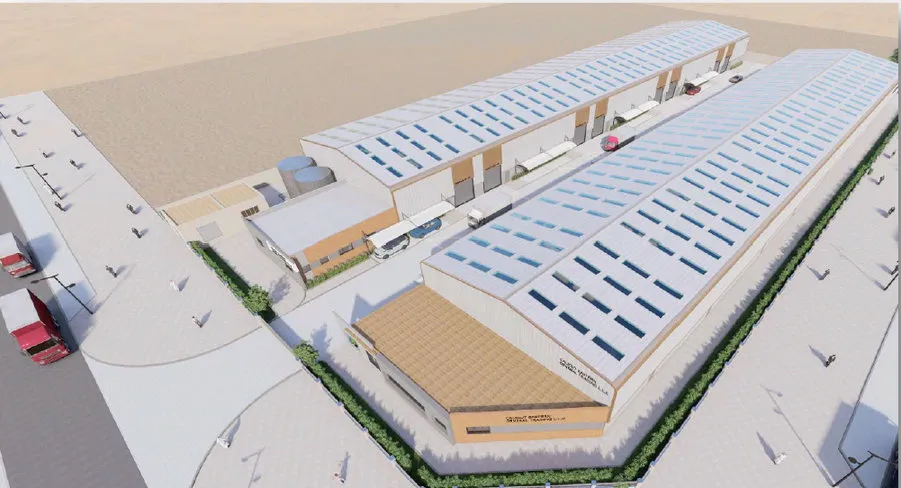
For the Acoustic Hall in Festival City, the connection design covered the roof truss nodes and splices of a column-free, U-shaped hall. On the Open Market Building at Qaryat Al Hidd in Abu Dhabi, with Khatib & Alami as consultant, the curved ribs of the long glazed vault were spliced and the rib splices designed through detailed connection analysis. On the DIC Warehouses, the rafter splices were designed with the haunched eaves and apex connections. See also our long-span steel roof design page.
Why choose a specialist steel splice design consultant
- Our engineers hold Dubai Municipality practice certificates, and we prepare Dubai Municipality submissions through to approval.
- A steel structure design consultancy: splice positions are set with the frame design, the transport limits and the erection sequence in one view.
- 96 projects completed across the UAE and the GCC.
- Our office is in Dubai Silicon Oasis, and we work across the UAE and the GCC.
Related pages
Steel connection design · Steel moment connection design · Gusset plate and bracing connections · High-rise steel structure design · Long-span steel roof design · All steel connection types
For steel splice design, contact our engineers.