Cable-stayed bridge design in the UAE brings together three structures that only work as one: a mast in compression, stay cables in tension and a deck that is both a beam and a compression member. Wrenze Steel provides the design of cable-stayed footbridges and feature bridges in Dubai and across the UAE, for real estate developers, municipalities, architects and engineering consultancies, contractors and steel fabricators. We design the mast, the stays and their anchorages, the deck, the bearings and the base connections, and follow the bridge through its construction stages to its final shape.
Our pedestrian bridge design page covers footbridges of every type, and our steel bridge design page covers pedestrian, link and vehicle bridges in general. This page covers the cable-stayed system itself.
Cable-stayed bridge design in the UAE: the system
A cable-stayed bridge is shaped by a few choices made at the start:
- Mast arrangement: a single mast, twin masts, an A-frame or H-frame pylon, or an inclined mast leaning away from the span
- Stay layout: a fan, with stays meeting near the top of the mast, a harp, with parallel stays, or a semi-fan between the two
- Cable planes: one central plane of stays, which needs a deck that is stiff in torsion, or two edge planes, which hold the deck against twisting
- Backstays: stays behind the mast tied to a back span or to ground anchors, which balance the forces from the main span
- Deck form: straight or curved in plan, with ramps or stairs at the ends
Each choice changes how forces travel. We develop the structural concept with the architect, so the form and the load path are settled together.
The mast
The mast works mainly in compression, with bending wherever the forces from the stays on each side do not balance. An inclined mast is held in balance by the stays and backstays. We check the mast for buckling with second-order effects, design the anchorage zone at the top where the stays arrive, and design the mast base and foundation for the overturning effect of the cables. The mast section is chosen for stiffness, appearance and the space needed inside it for anchorages and inspection.
Stay cables
Footbridges use several cable types: spiral strands and full-locked coil strands with socket end fittings, steel tension bars for short stays, and parallel strand systems for heavier bridges. Stays are designed for their working force as a fraction of the minimum breaking strength, following the Post-Tensioning Institute recommendations for stay cables (PTI DC45.1) or EN 1993-1-11 as the specification requires. Long stays sag under their own weight, which reduces their effective stiffness, so the analysis includes cable sag. Fatigue at the sockets and anchorages is checked for the repeated loading from pedestrians and wind.
Cable anchorages at deck and mast
Each anchorage is a concentrated load point where a large cable force enters the steel structure at an angle. We design the full path of that force:
- End fittings and pin plates: fork sockets connect through pins to gusset plates on the cable line, designed as pin-connected members to AISC 360
- Load spreading: stiffeners, anchor boxes and diaphragms carry the force into the deck girders and the mast walls without local yielding or buckling
- Welds: welds sized for the cable force and its fatigue range, to AWS D1.1
- Adjustment and access: length adjustment for tensioning, and access to inspect and replace each cable
Complex anchorages are checked by finite element connection design, as described on our steel connection design page.
The deck
Because the stays are inclined, they push the deck towards the mast as well as holding it up. The deck is designed as a beam-column, for bending and compression together. With a single plane of stays or a curved deck, torsion is significant, so a box section or a stiff torsional frame is used. Bearings and expansion joints at the abutments let the deck move with temperature, and the deck is checked for wind across it and for uplift.
Construction stages and cable tensioning
The final shape of a cable-stayed bridge depends on how it is built. We set the cable pretensions so the deck reaches its target profile under permanent load, then follow the structure through each erection stage, from temporary supports to the release of the deck onto the stays. The design gives the fabrication geometry, the camber, the tensioning sequence and the target forces at each stage, with tolerances for checking the forces on site.
Cable loss, robustness and vibration
- Single-cable loss: the bridge is checked with any one stay removed, including the dynamic effect of a sudden loss, so the deck and mast remain stable during an accident or a cable replacement.
- Footfall vibration: we calculate the vertical and lateral natural frequencies of the full system. Where they fall below the AASHTO minimums of 3.0 Hz vertical and 1.3 Hz lateral, the response to walking and crowd loading is calculated and kept within comfort limits.
- Cable vibration: long stays are checked for wind-induced vibration, with dampers where needed.
Analysis and design
A cable-stayed structure stiffens and redistributes force as it deflects, so it is analysed with geometric nonlinear analysis, including large displacements, P-Delta effects in the mast and deck, tension-only stays and cable sag. Design follows AISC 360 for the steel structure, the AASHTO LRFD Guide Specifications for the Design of Pedestrian Bridges for pedestrian loading and bridge checks, ACI 318 for the foundations and ASCE 7-16 for wind and seismic loading, together with Dubai Municipality or the authority of the project’s emirate, and the roads authority where the bridge crosses a public road.
What our cable-stayed bridge design consultants deliver
- A structural concept developed with the architect, with the mast, stay and deck arrangement
- Structural calculations for the mast, stays, deck, bearings and foundations interface
- Connection designs for the cable anchorages, splices and base connections
- Design drawings, fabrication geometry and camber, and the tensioning sequence with target forces
- Support reactions for the foundation designer
- Calculations and drawings for authority approval, and technical support during construction
How a cable-stayed bridge project runs
- You send the architectural concept, the site survey and the clearances required over the road, path or water.
- We agree the scope, the programme and the approval route.
- We develop the structural concept and compare the arrangements.
- We complete the nonlinear analysis, the construction stage analysis and the member and connection design.
- We issue the calculations and drawings and support the project through construction.
Cable-stayed and bridge projects
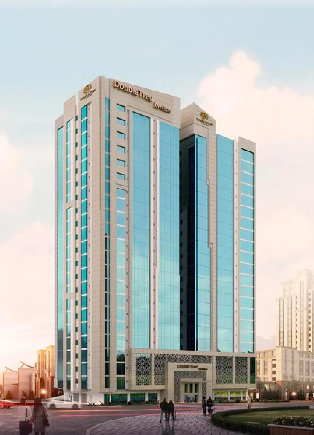
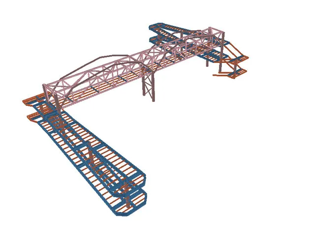
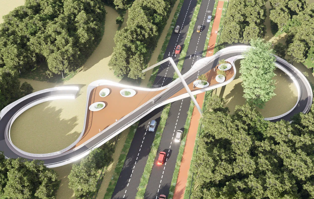
Dubai Municipality appointed Wrenze Steel to provide full consultancy for the Mushrif Park cable-stayed bridge in Dubai, a curving steel deck with looped ramps crossing a road through the park, carried by stays from a single inclined mast. Our role ran from structural concept to construction-stage technical support: geometric nonlinear analysis, tension-only stays with cable sag, pretension set for the target deck profile, single-cable loss, modal analysis for footfall vibration and the design of the cable anchorages at deck and mast. We also carried out the steel design verification and 3D modelling of a twin-arch pedestrian bridge for Parsons in Dubai, designed the cable anchorage connections of the Brazil Pavilion at Expo 2020 for 650 kN cable fittings, and designed the DoubleTree link bridge between twin towers in Ras Al Khaimah.
About Wrenze Steel
- Our engineers hold Dubai Municipality practice certificates, and we prepare Dubai Municipality submissions through to approval.
- A steel structure design consultancy: cable-stayed and other steel bridges are part of our work alongside buildings and industrial structures.
- 96 projects completed across the UAE and the GCC.
- Our office is in Dubai Silicon Oasis, and we work across the UAE and the GCC.
Related pages
Pedestrian bridge design · Steel bridge design · Link bridge design · Tensile structure design · All steel structure types
For a cable-stayed bridge, contact our engineers.